-
-
Proceed with steps of a quarter turn each and check the height of the blades in the carriage before each further turn.
Figure Mashine
Figure Carriage
Safety note
Caution: Risk of injury!
Please be careful when using the shaping machine and always watch the blades during use to avoid personal injury and damage to the machine. The cutting edges are very sharp. Processed cane may get sharp edges, which can cause damage and considerable injuries. Please carefully remove the blades before maintenance and adjustments.
The shaping machine is a professional reed making machine and should be kept out of the reach of children. The machine must not be used by persons with reduced physical, sensory or mental capabilities.
Before use, always ensure that it is securely fixed to the work surface. It is best to use the supplied C-clamp for this purpose.
Transportation Lock
Before use, remove the transport protection clamped between the cane holder (8) and the shaper form (13) and fold the holder for the locking handle (7) backwards. Avoid dropping the locking handle onto the shaper form, as it may be damaged, as well as the cane holder and its blade.
To prevent damage during transport, pull the transport protection over the cane holder before closing the locking holder. The cane holder must never be closed without a mounted shaper form or a corresponding spacer. Otherwise there is a risk of deforming the spring loaded Stop (9).
Shaping Cane
Position the gouged cane centered on the shaper form. If necessary, you can use the included centering pins (24) (see 9. inserting the centering pins). The outside of the cane faces upwards, the inside lies on the shaper form (13). Push the cane towards the stop (9). There should be an equal amount of cane protruding to the left and right of the shaper form. The symmetry of the finished shaped cane depends to a large extent on this alignment. Then carefully place the cane holder (8) on the cane and check again that the position has not changed before shaping. Now push the locking handle (4) backwards. This will fix the cane onto the shaper form and at the same time the scoring knife will score the cane in the center.
Slide the carriage (10) as far back as possible.
Move the blades along the shaper form with light pressure. Start just before the center and continue the cut evenly to the front end of the shaper form. To shape the other side, push the carriage as far forward as possible and place the other sides of the blades on the shaper form. This cut also starts just before the center and is carried out to the end of the shaper form.
To remove any protruding cane or single fibers, this step can be repeated several times.
Release the locking handle and fold the holder back to remove the finished shaped cane from the shaping machine.
Tip: Preparation of The Cane
Soak the cane in water for one to two minutes before shaping. Keep the soaking time as short as possible. The shorter the canes are soaked, the cleaner the cut will be. If a lot of force has to be applied or cracks occur, the cane is still too dry and may need to be soaked a little longer.
Adjusting The Length
The sliding length of the carriage (10) must be set to match the selected shaper form (13). The blades (11) must be able to cut at least along the entire shaper form but must not cut into the stop (9) or touch each other after the shaper cut.
The sliding length is adjusted to the ordered shaper form. After a change to a different shaper form, the tubes on the axis (6) may have to be adjusted. To do this, use the tube included in the accessories box.
Insert the blade holders (14) into the carriage. Push it in the direction of the stop until the blades reach the end of the shaper form, but do not protrude beyond it.
If the blades touch the stop, the piece of tube must be replaced with a longer one. To do this, cut off a piece of the supplied tube. In order for this to be slipped over the axis, it must be cut open along the side.
Continue in the same way with the front carriage limit. Pull the carriage towards you until the front blade edges reach the end of the shaper form, but cannot touch each other. Position a matching tube piece (40) on the axis.
Adjusting The Clearance of The Carriage
If the carriage moves unsteadily, bucks or jams during shaping, the carriage (10) and the guide part (5) must be cleaned and the carriage clearance must be readjusted. To do this, loosen the two grub screws on the sides of the carriage with an hex wrench no. 2. Use a slotted screwdriver to adjust the position of the two ball bearings (27) completely to the outside with the aid of the excenters (15).
Tilt the carriage to the right against the guide part with one hand. Now adjust the position of the left ball bearing with the help of the excenter so far inwards that the carriage has the same distance to the guide on the left and right. Then adjust the right excenter so that the carriage can no longer be tilted to the left or right.
The carriage clearance is set correctly when the carriage can no longer tilt and can be moved smoothly along the axis.
Finally, the grub screws for fixing the excenters are tightened again to secure the set carriage clearance.
Changing & Adjusting The Blades
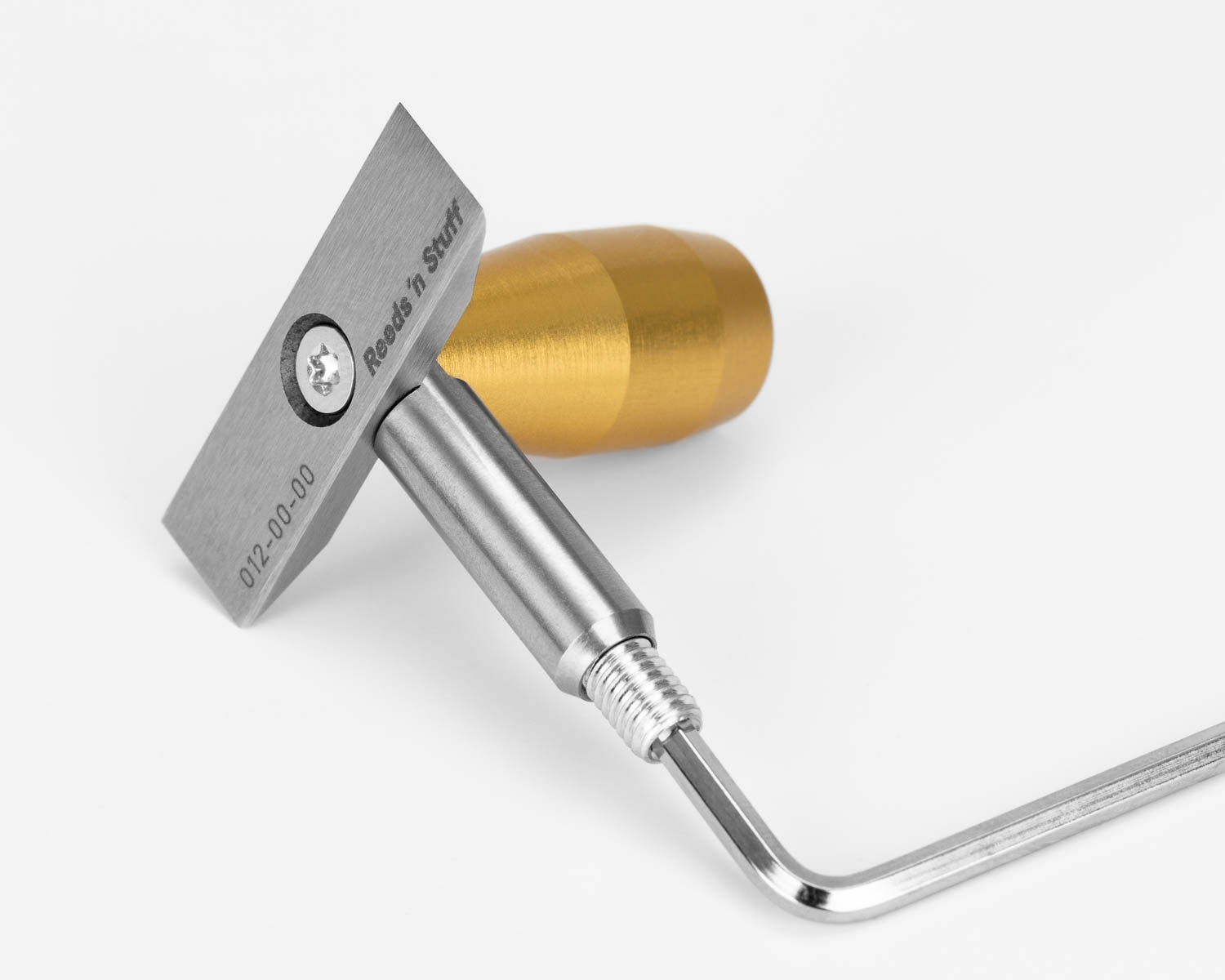
To change the blades, remove the blade holders (14) from the carriage (10) of the shaping machine. Now loosen the fastening screw with the supplied T10 Torx screwdriver to remove the handle (12) and to be able to remove the old blade (11). Place the back of the new blade on the support surface on the blade holder with the corresponding engraving, OB or EH (See 8. Adjusting the Blade Holder for your Instrument and Figure 3).
Then secure the new blade to the handle and blade holder with the screw. Completely unscrew the grub screw on the underside of the knife holder and then screw it back in with two turns. Now place the complete blade holder back into the carriage and repeat the process for the second blade holder.
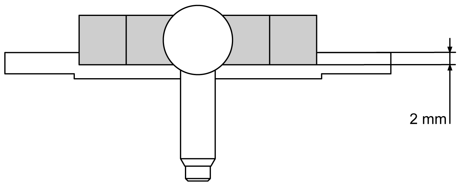
Figure 1
For new blades, the height at which the blades are to cut must be readjusted. For this purpose, the height difference between the lower edge of the blades and the surface of the shaper form (13) is measured. As a starting position, a distance of approximately 2 mm is recommended, as shown in the figure. To set this, turn the grub screw in the blade holder until the desired height is reached.
After you have adjusted the blade of the first side, repeat the procedure for the second blade. The cutting edges of the blades can be used almost completely by even and regular readjustment. You can readjust the blades several times until the tops of the blades are approx. 1.0 mm above the cane. After that, replacement is necessary.
Adjusting The Blade Holder
The distance between the blades (11) must be selected depending on the used shaper form (13). If you purchase a shaping machine including a shaper form, the blade distance is already set correctly. If you change the shaper form, the distance between the blades may have to be adjusted. All Reeds 'n Stuff shaper forms are uniquely named and assigned to an instrument by engraving. Please refer to the following list for the required blade distance:
| Instrument | Engraving– Blade distance |
|---|---|
| Oboe | Oboe – 10 mm |
| Oboe Le Roseau Chantant | Oboe – 10 mm |
| Oboe d'amore | Oboe – 10 mm |
| Viennese Oboe | Oboe – 10 mm |
| English Horn | EH – 13 mm |
| Baroque Oboe | EH – 13 mm |
| Bass Oboe | EH – 13 mm |

Figure 2

Figure 3 – Engraving (OB / EH) must point to the back of the blade, here you can see the setup for Oboe.
The letter markings "OB" and "EH" are engraved on the blade holder (14). Referring to the list, the blades must be attached to the corresponding sides (Figure 2). The following applies: The distance between the blades in the shaping machine is smaller for oboe canes than for English horn canes.
The back of the blade is placed on the surface with the matching engraving and fixed with the screw (see Figure 2). This step must be performed for both blade holders. For further instructions on installing the blades, refer to the section "Changing & Adjusting The Blades".
Inserting The Centering Pins
Depending on the maximum cane width, up to four cylindrical pins (24) can be inserted in the carriage (10) for better centering of the canes on the shaper form. Possible distances are 8, 9, 12 and 12.5 mm. Select the matching distance according to the width of your canes. Insert the pins in the centering holes (41) in the carriage.
Figure 4
Machine Care
The lifespan of your machine is optimized by regular care. Dry and clean the shaping machine after each use and remove cane remains and any dirt. Use a soft cloth or a brush for this purpose. To ensure the smooth operation of your shaping machine, you can occasionally apply a little acid and resine free oil to the ball bearings (31), their guide (5) and the axle (6).
Do not oil or grease the locking handle (4) and the cylinder pin for locking or keep it free of grease to ensure secure fastening of the cane. The latest generation shaping machine with synthetic bearings no longer requires greasing of the axle.
Installing The Shaper Form
Fold the cane holder (8) and the locking handle back (7) so that the guide (5) is uncovered. Prepare the two required fastening screws and the matching screwdriver. Place the shaper form (13) you want to install with the slot on the bottom side on the guide. Now apply slight pressure downwards to the shaper form with one hand and push it backwards against the stop (9) until both holes of the shaper form are above the threaded holes of the guide.
Now insert the enclosed screws into the threaded holes and fasten the shaper form to the guide. Do not use excessive force; hand-tightening the screws is sufficient. Do not release the shaper form until both screws are tightened.
Adjusting The Cane Holder
If the cane is not held evenly on the shaper form (13), the cane holder (8) must be adjusted. This step is necessary if the fixed cane moves during shaping or if no clear scoring can be seen in the center of the shaped cane. Another indication is that the cane holder is not parallel to the shaper form viewed from the side.
To do this, place a piece of cane that has not yet been shaped on the shaper form and push it to the back of the stop. Place the cane holder on the cane without locking the locking handle (4).
The two set screws on the left and right of the fastening screw adjust the position of the cane holder in relation to the locking holder (7). You can imagine the principle similar to a rocker.
For smaller corrections, adjustment through these two set screws is sufficient. For a larger correction, it may be necessary to slightly loosen the middle fastening screw of the cane holder on the top of the locking holder.
Correct the position of the can holder on the side where it is too high, which is the side where it does not properly lock the cane. To do this, turn the set screw into the locking holder until the pin rests on the top of the cane holder. Proceed in small steps until the cane holder is parallel to the shaper form again. If the set screw cannot be turned further into the locking holder on this side, you can alternatively turn the set screw out a little on the other side, as with a rocker.
Both set screws should rest on the cane holder so that it is held in place without applying too much force to it.
Now you can tighten the middle fastening screw again.
When replacing the cane holder, only the middle fastening screw has to be loosened. This screw is then used to reattach the new cane holder.
Finally, insert a piece of cane into the shaping machine and push the locking handle backwards, to check the alignment. If there is no gap between the cane and the cane holder and the cane can no longer be moved, the cane holder is precisely adjusted. The cane should have a well-defined scoring in the middle. It should be possible to push the locking handle as far back as possible, without touching the limiting pin at the back. A distance of 0.5-1.0 cm is ideal here.
Klemmen Sie abschließend ein Holz zur Überprüfung der Ausrichtung in den Fassonschneider ein. Ist zwischen Holz und Niederhalter kein Spalt mehr zu sehen und lässt sich das Holz nicht mehr bewegen, ist der Niederhalter exakt eingestellt. Das Holz sollte zudem eine gut ausgeprägte Kerbe in der Mitte besitzen. Der Verriegelungsgriff sollte möglichst weit nach hinten gedrückt werden können, den hinteren Begrenzungsstift jedoch nicht berühren. Ein Abstand von 0,5-1,0 cm ist hier ideal.
If necessary, repeat the process until the desired result is achieved.