-
-
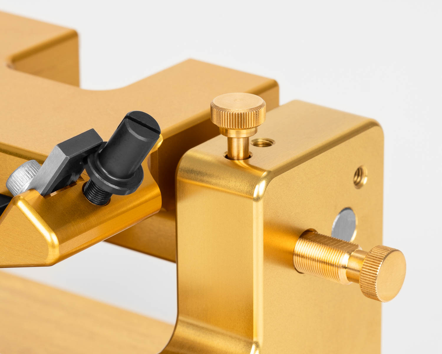
Prior to using the machine, please remove the transport lock screw.
-
-
In order not to lose it, the transport lock can be screwed into the hole provided on top of the tower on the right-hand side.
Figure Machine
pending
Figure Carriage
pending
Transport Lock
Profiling the Reed
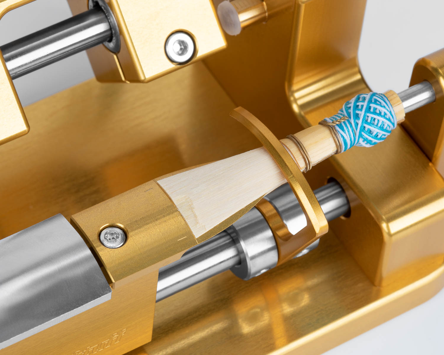
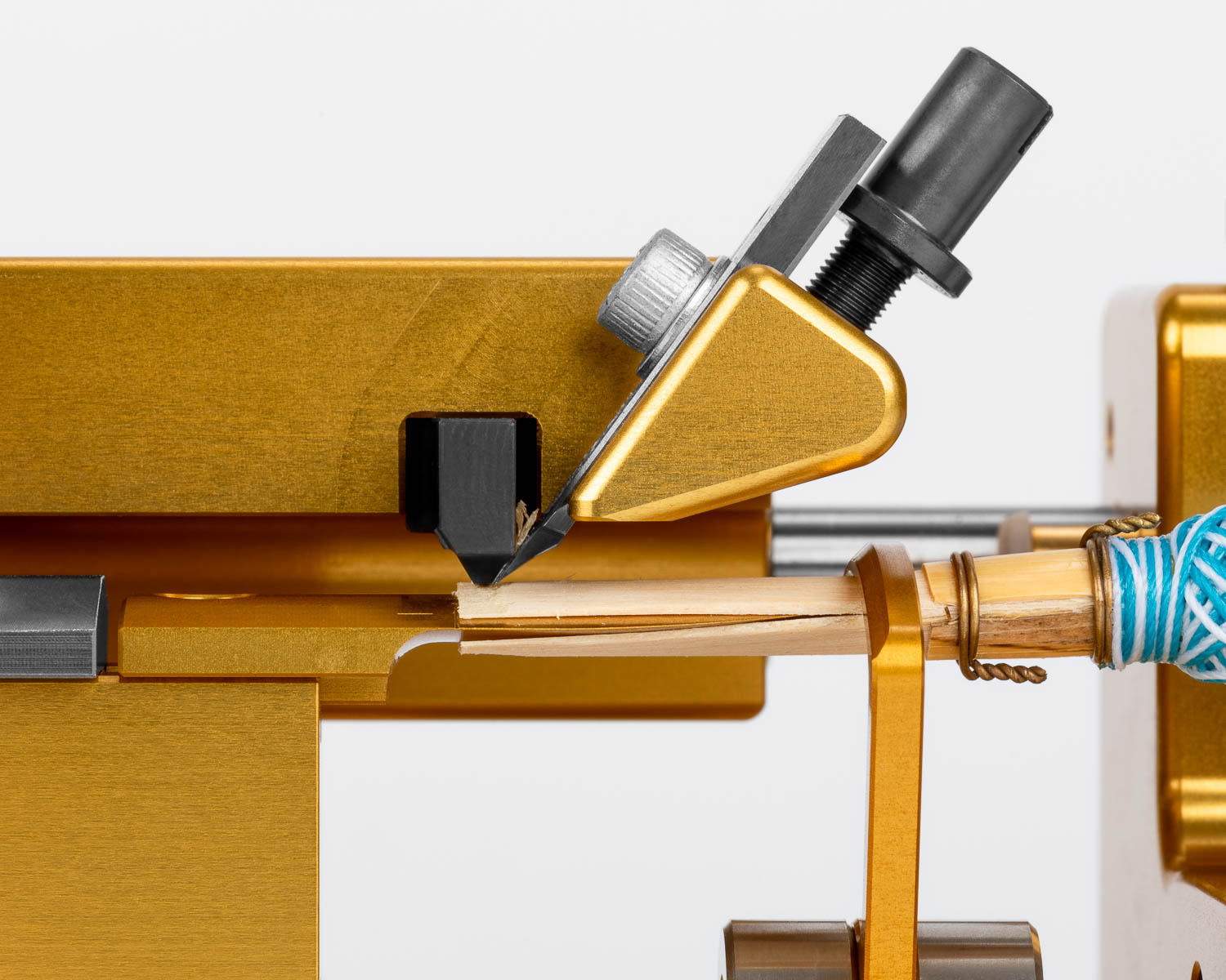
Soak the reed before profiling. This will extend the life of the blade, as well as produce better results. Clip the reed to the desired length and place it on the tongue. Insert the mandrel, then make sure the tip of the reed is lined up with the line on the tongue.
-
-
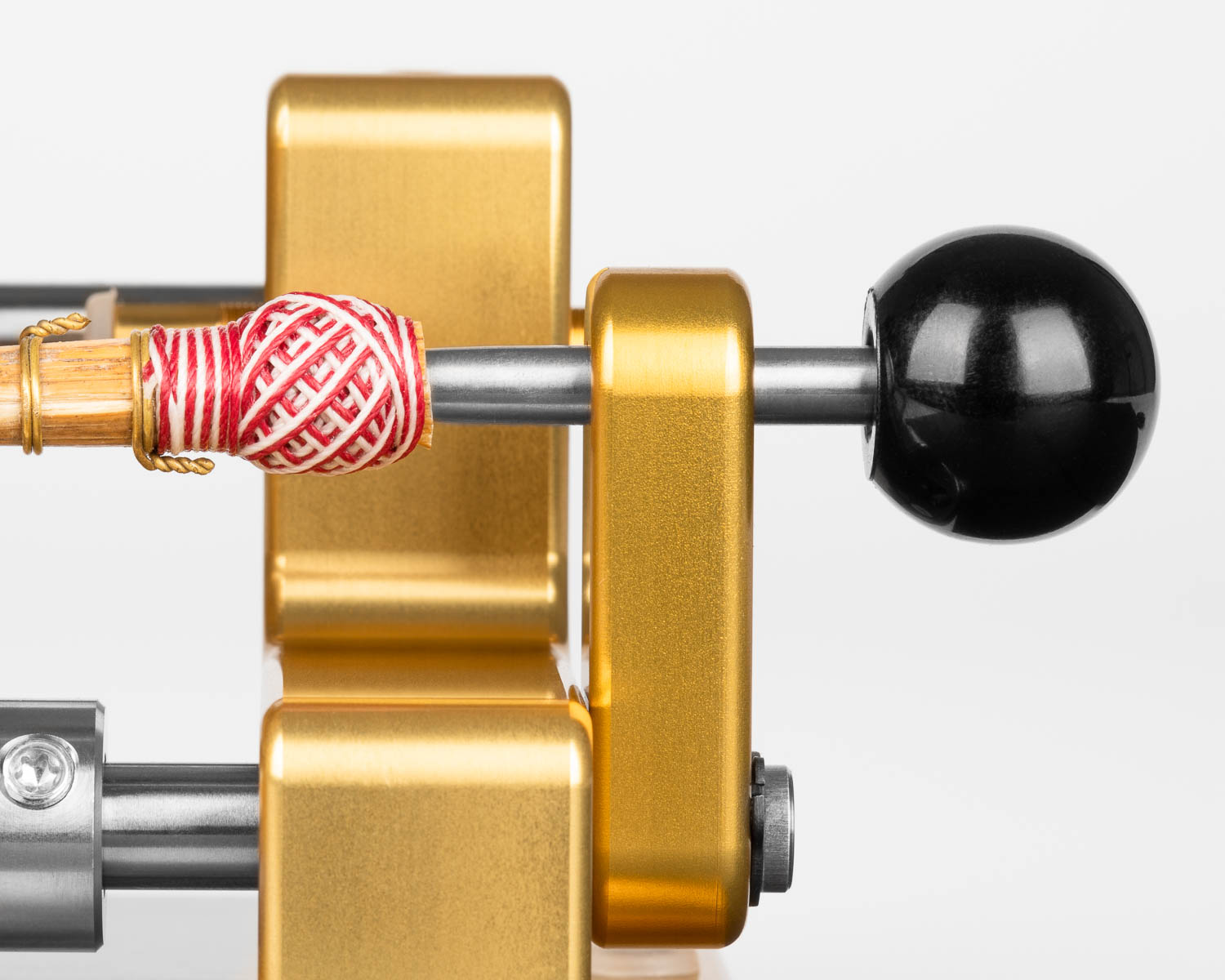
We recommend leaving 7 - 8 mm distance between the mandrel holder and the black ball of the mandrel.
The reed can then be clamped into place using the rotating clamp. Double-check that the reed is centered on the tongue with the help of the centering lines.
To profile, push the carriage from the back towards the front of the reed. The rotating handle is used to rotate the axle. Be sure to do this in small increments, and not to turn as you profile.
Before profiling the entire length, pass over the first 2 mm of the blade with the tip profiler to remove a good amount of the cane at the tip. This will help ensure that as you profile, the corners do not tear out.
Adjusting the Overall Thickness
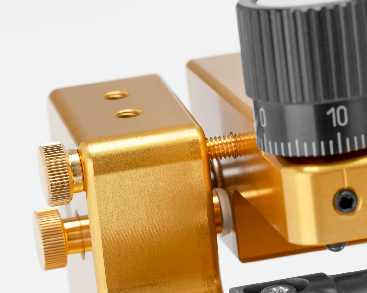
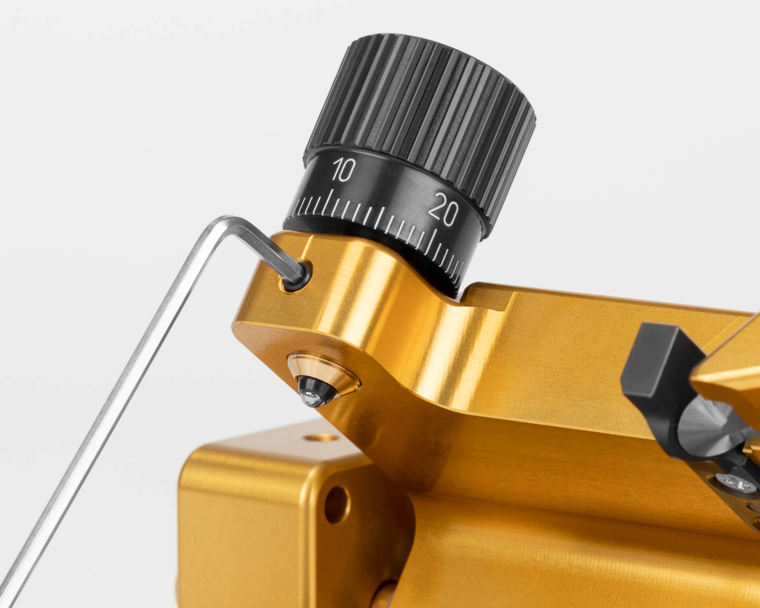
Each line on the micro-adjuster represents a change in thickness of about 0.01 mm.
-
-
To adjust the overall thickness, first loosen the set screw at the front of the carriage.
Turning the micro-adjuster clockwise will result in thicker reeds, while turning counterclockwise will results in thinner reeds.
After adjusting the thickness, tighten the set screw again. As the tip of the set screw is made of plastic, do not overtighten this screw.
Once you have adjusted the thickness, ensure that the blade does not come into contact with the tongue. This will damage the blade and tongue.
Adjusting the Tip Length
After loosening the set screw for the template, the length of the tip can be adjusted by moving the template.
Moving the template closer to the tongue will lengthen the tip area, while moving it away from the tongue will shorten the tip area.
The change in position can be monitored through the scale on the side.
Adjusting the Profile Length
The travel length of the carriage is limited by the two screws with plastic heads on either side of the machine. These are secured by fixing screws. Once these set screws are loosened, the adjustment screws can be loosened or tightened to adjust the length of the profile. As the set screws are made of plastic, please do not overtighten them.
The adjustment screw on the left side is set up so that the blade only barely moves beyond the tip of the reed, and that the ball bearing does not end up in the opening for the template set screw.
The adjustment screw on the right limits how far up the blade of the reed the carriage will travel. Please be careful when adjusting the travel length, that the blade does not collide with the reed clamp.
Changing Templates
After removing the set screw for the template, the template can be removed and replaced.
Once the new template has been attached, and the set screw tightened, please ensure that the blade does not come into contact with the tongue. This could damage the blade and the tongue.
This might require adjusting the overall thickness with the micro-adjuster.
Setting up or reseting a template
The following table provides the most crucial measurements for setting up the templates on the tip profiling machine.
The position and thickness measurements given are guidelines used by the factory, and are meant to help you reset your machine or find a starting point after having changed templates.
The given Length of Scrape is the factory setting, most templates allow for a longer scrape than how the machine is delivered. This allows for flexibility in finding an individualized setup for each user.
Generally it is only necessary to profile the first few millimeters of a sacrificial blank to set up a tip profiling machine. Utilizing this method, one blank can be clipped several times and used to set up several machines.
Machines delivered from the factory are set up with these measurements and the dial then calibrated to zero.
| Template |
Distance to Line (Gen1) |
Distance to Line (Gen2) |
Thickness at Center (Tip of Reed) |
Length of Scrape |
|---|---|---|---|---|
| FG1 | 61.20 mm | 61.10 mm | 0.31 - 0.32 mm | 15 mm |
| FG2 | 61.20 mm | 61.10 mm | 0.34 - 0.35 mm | 15 mm |
| FG3 | 61.10 mm | 0.34 - 0.35 mm | 15 mm | |
| GR | 60.50 mm | 61.10 mm | 0.30 mm | 14 mm |
| GR5 | 61.50 mm | 61.10 mm | 0.30 mm | 14 mm |
| PM | 60.95 mm | 61.10 mm | 0.34 - 0.35 mm | 15 mm |
| LM3 | 60.30 mm | 61.10 mm | 0.30 mm | 19 mm |
| VZ | 61.20 mm | 61.10 mm | 0.34 - 0.35 mm | 18 mm |
| DJ | 61.50 mm | 61.10 mm | 0.32 - 0.33 mm | 18 mm |
| THOM | 61.20 mm | 61.10 mm | 0.34 - 0.35 mm | 15 mm |
| HER1 | 60.20 mm | 61.10 mm | 0.20 mm | 15 mm |
| BOSA | 61.10 mm | 0.21 mm | 15 mm | |
| ARB | 61.10 mm | 0.38 mm | 15 mm | |
| VR1 | 61.10 mm | 0.29 mm | 20 mm | |
| TS1 | 61.10 mm | 0.18 mm | 18 mm | |
| KFH1 | 61.20 mm | 61.10 mm | 0.40 mm | 17 mm |
| KFH2 | 61.20 mm | 61.10 mm | 0.43 mm | 17 mm |
-
-
Distance to Line is measured from the far end of the template to the engraving line on the tongue of the tip profiling machine.
-
-
-
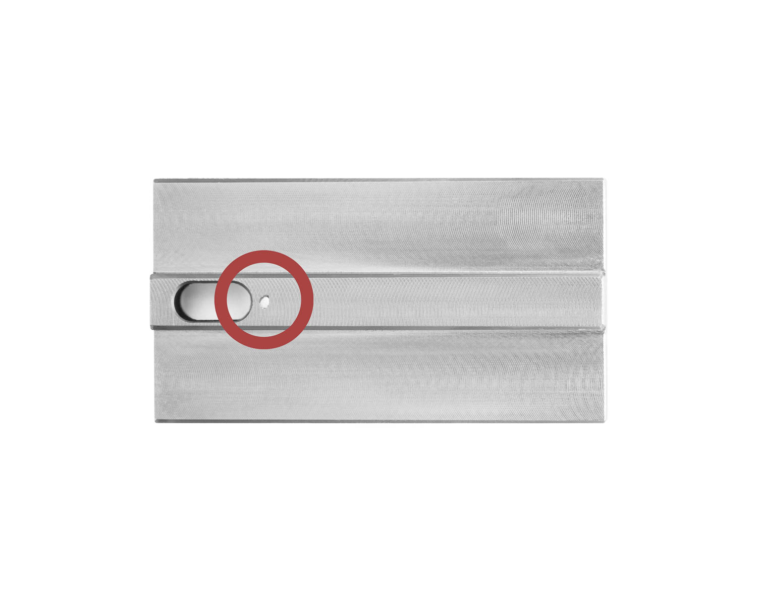
Gen2 templates are identified by an engraved dot on the underside of the template.
Changing Tongues
To change or replace the tongue, simply remove the set screw. Once it has been removed, the tongue can be replaced.
Once the new tongue has been attached, and the set screw tightened, please ensure that the blade does not come into contact with the tongue. This could damage the blade and the tongue.
This might require adjusting the overall thickness with the micro-adjuster.
Thickness Calibration
You can re-center the scale to “0” once you are satisfied with the result. Another option is to set the scale to your tip thickness if you prefer.
Loosen the set screw on the thickness adjustment knob and rotate the scale to zero or any other number you want to set. Then retighten the set screw.
Replacing and Adjusting the Blade
Loosening or removing the set screw will enable the blade to be replaced or adjusted. Adjusting the blade position works best when the set screw is snug against the blade, as this light friction will ensure that the blade is not moving too much at once.
After replacing or adjusting the blade, re-tighten the set screw firmly so that the blade is securely fastened.
Once the blade has been replaced or adjusted, and the set screw tightened, please ensure that the blade does not come into contact with the tongue. This could damage the blade and the tongue.
Adjusting the blade is best done with the use of a Blade Adjustment Indicator, as achieving the ideal shaving thickness of 0.03 mm is nearly impossible without the aid of a dial indicator.
Adjusting the Position of the Clamp
The position of the reed clamp can be adjusted. Loosening the screws on the positioning rings on either side of the clamp allows the clamp and rings to be moved to a desired position. Once this position has been attained, tighten the screws on the positioning rings.
Please ensure that the clamp does not come into contact with the blade, as this can lead to damage.
Replacing the depth gauge
If the depth gauge is worn out, it can be replaced by removing the screws and pulling straight out. When inserting the new depth gauge, be sure not to bend the setting pin, as this helps ensure the correct positioning of the depth gauge.
The blade must be removed before replacing the depth gauge.
Changing from Bassoon to Contrabassoon
The tip profiling machine can be converted from a bassoon to a contrabassoon machine with a few simple steps.
The Contra Exchange Set contains all the parts you will need.
Safety Instructions
Please always be careful while using your Reeds 'n Stuff product. The blades used in our machines, and reed making in general, are very sharp and may cause injuries and other damage.
In order to avoid negative consequences, you should follow the following safety instructions during installation, usage and maintenance of your machine:
Reeds 'n Stuff products are not a toys. They are therefore not to be used by children and persons with limited physical, sensory or mental abilities.
Reeds 'n Stuff products are intended to be used indoors.